Bolted fault current calculation is a fundamental part of IEEE 1584 guidelines for arc flash analysis. Here’s how it’s calculated and the effect of ground resistance:

How is the Bolted Fault Current Calculation in IEEE 1584-2018 Done?

Bolted fault current is the theoretical current that would flow in the event of a direct (zero-impedance) short circuit, such as if conductors were clamped together without any impedance between them. It’s calculated based on several parameters of the electrical system, including:

  1. System Voltage: The voltage level of the equipment or part of the system where the fault is assumed to occur.
  2. Impedance of the Power System: This includes the impedance of the transformer, cables, and any other devices within the fault loop that may limit the current.
  3. Transformer Characteristics: Including kVA rating, impedance percentage, and primary and secondary voltage.

IEEE 1584 primarily focuses on the bolted fault current because it’s the foundation for determining incident energy and arc flash boundary in a system.

Role of Ground Resistance per IEEE 1584 – 2018

Ground resistance does not play a significant role in the calculation of bolted fault current. Since bolted faults are assumed to have negligible impedance, the current is not influenced by the resistance in the ground path. However, ground resistance may impact other types of faults, such as line-to-ground faults, where impedance in the ground path could affect fault current levels and distribution.
For arc flash studies, IEEE 1584 – 2018 assumes a worst-case bolted fault condition (typically three-phase faults), which simplifies calculations by ignoring the effect of ground resistance, providing conservative estimates for safety.

Definitions Screen Shot from the Standard:

available short-circuit current: At a given point in a circuit, the maximum current that the power system can deliver through a given circuit to any negligible-impedance short circuit applied at the given point, or at any other point that causes the highest current to flow through the given point. “Available short-circuit current” and “bolted fault current” are equivalent for a zero fault impedance.

bolted fault: A short-circuit condition that assumes zero impedance exists at the point of the fault.


Case of Resistance and calculations from the Study
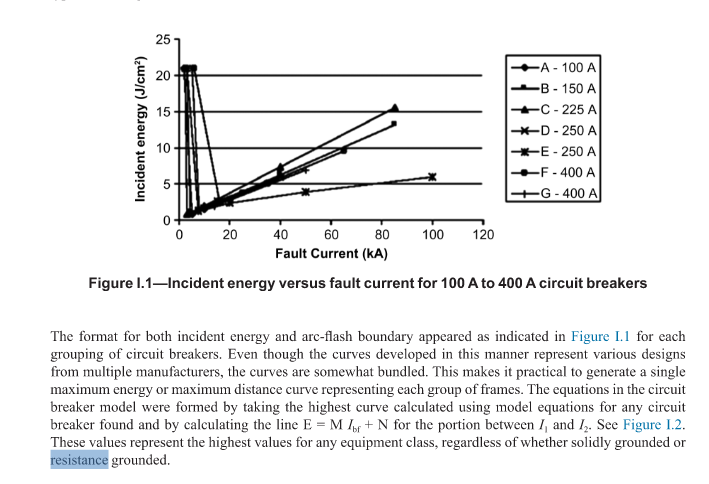
Fault Currents and Ground Resistance

Understanding bolted fault current is essential for accurate arc flash analysis and electrical safety planning. By following IEEE 1584-2018 guidelines, you can ensure safer work environments and compliance with industry standards. For any electrical system, calculating the bolted fault current provides a foundation to evaluate potential incident energy levels and establish necessary arc flash boundaries. Ready to enhance the safety and compliance of your operations? Contact Us today to get expert support on bolted fault current calculations, arc flash studies, and comprehensive electrical safety assessments.

Other Recent Articles

Arc Flash Study Report

How to Read Your Arc Flash Study Report: A Plain-English Guide for Facility Managers

An arc flash study report tells you how much energy could be released at each point in your electrical system during a fault, what protective equipment workers need, and where your highest-risk areas are. The problem is that most of these reports are written by...
EV Charging Infrastructure

EV Charging Infrastructure and Electrical Safety: What Facilities Need to Know Before Installing

Adding EV chargers to a commercial or industrial facility introduces electrical safety risks that go well beyond the installation itself. Ground fault exposure increases in wet parking environments. Arc flash incident energy values can change at panels and switchgear...
Electrical technician performing preventive maintenance.

The Facility Manager’s Guide to Electrical Maintenance Intervals: What to Do and When

Electrical equipment rarely fails on a convenient schedule. It fails when a connection has been loosening for months, when a breaker hasn't tripped correctly in years, or when load has crept up past what the original study accounted for. The good news is that almost...
Electrical technician inspecting an industrial control panel to improve electrical safety and reduce arc flash risks.

Why Your Insurance Carrier Is Asking About Arc Flash Studies (And What to Do About It)

A renewal questionnaire lands on your desk, and somewhere between the sprinkler inspection dates and the roof age, there's a new line item: Do you have a current arc flash study? For a lot of facility managers, that question comes out of nowhere. The equipment hasn't...

Can Your Electrical System Handle the Next Load? Why 30-Day Metering Matters Before Adding EV Chargers, Tenant Panels, or Major Equipment

Adding electrical load to an existing facility can feel like a straightforward decision at first. A tenant needs more power. A company wants to install EV chargers. A manufacturing facility is adding a new piece of equipment. A property owner is planning upgrades to...
Electrical engineering consultant performing diagnostic measurements with a multimeter during a site inspection

What Does an Electrical Engineering Consulting Scope of Work Actually Include?

An electrical engineering consulting scope of work defines the studies, deliverables, standards, timeline, assumptions, and exclusions for a project. Use this guide to compare proposals and identify gaps before work begins.

Thermographic Scanning for Arc Flash Risk Reduction

How Thermographic Scanning Supports Arc Flash Risk Reduction Strategies

Arc flash assessments and thermographic scanning are often treated as separate line items on a facility's safety budget: two independent services, scheduled independently, producing separate reports that live in separate binders. That separation is a missed...
Infrared Thermography for Seasonal Maintenance

Infrared Thermography for Seasonal Maintenance: Why Timing Matters

Infrared thermography is one of those tools that gets more powerful the smarter you are about when you use it. The technology itself, a thermal camera that reads heat signatures through surfaces without contact, is well understood. The part that most facilities get...
ROI of Power System Studies

The Hidden ROI of Power System Studies: Downtime Prevention and Cost Savings

Power system studies do more than support compliance—they help prevent costly downtime, reduce liability, and improve electrical reliability. This article explains how load flow, short circuit, arc flash, and coordination studies deliver measurable ROI for facilities in healthcare, manufacturing, data centers, and other critical environments.

NFPA 70E Training

Is Your NFPA 70E Training Program Audit-Ready?

Learn how to structure and document your NFPA 70E training program to pass regulatory audits, satisfy OSHA, and protect your organization from liability.